|
Ardpicprog
|
This page describes the circuit and construction of a PIC programmer that supports a number of common 14-bit PIC devices, such as the PIC16F84, PIC16F84A, PIC16F628A, and PIC12F675.
Other PIC devices that run off 5 volts and use a 13 volt programming voltage (VPP) may also work with some minor modifications to the circuit, or via an adapter cable plugged into the ICSP header. See the supported device list for a breakdown as to whether the ZIF socket or an ICSP adapter cable must be used with each type of device.
The programmer has the following features:
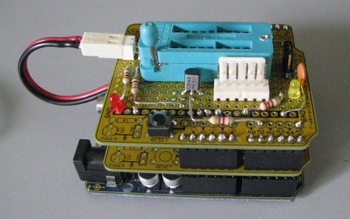
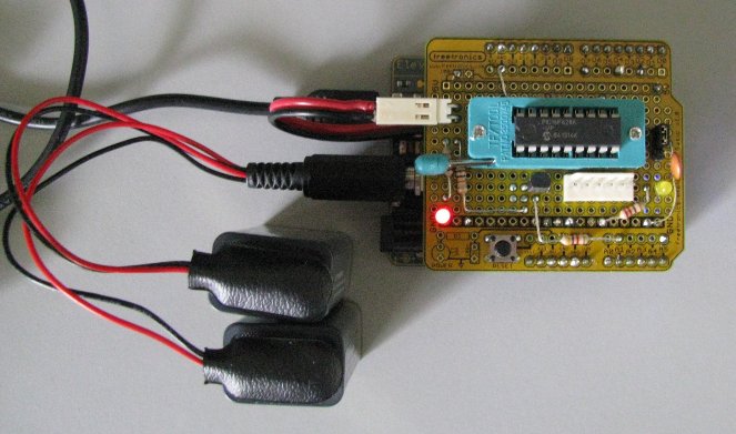
The PIC programmer is built on two shields stacked on top of each other, with the 13 volt power supply on the bottom shield and the PIC programming circuitry and ZIF socket on the top shield. A full parts list is given at the bottom of this page. The following photo shows the fully assembled PIC programmer mounted on top of an Arduino Uno compatible main board:
This section describes a very simple 13 volt power supply based on a common 7812 voltage regulator that has been tested by the author. Community members have contributed designs for DC-to-DC step up converters that may also work that are driven by the Arduino's 5V rail. See the page on alternative 13 volt power supplies for more information.
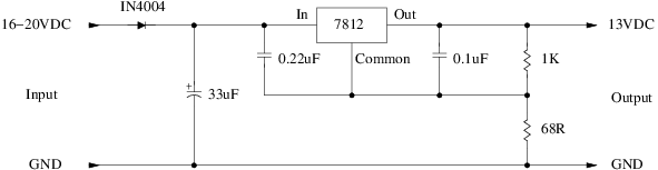
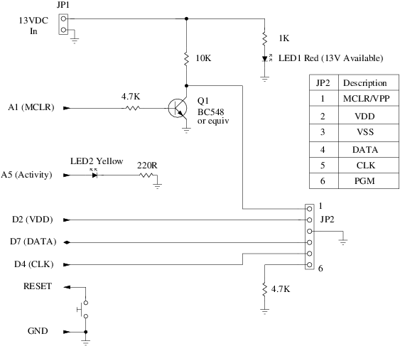
We start with the power supply for the 13 volt programming voltage (VPP). In this design we will use an external source of between 16 and 20 volts DC as input. We will use an ordinary 12V voltage regulator with a resistor ladder in the output stage to generate the 13 volts we need:
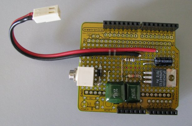
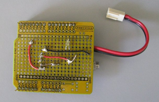
The circuit is built on an Arduino prototyping shield, with all of the components lying flat so they don't interfere with the main circuit board we will be putting on top later. The following photos show the top and bottom of the power supply board:
Note: while the power supply is built on an Arduino prototyping shield, it does not connect to any of the Arduino power or I/O pins. Not even the ground pin. The 13 volt supply could therefore be built into a separate enclosure instead of on a shield.
We used a 3.5mm monophonic headphone jack for the external power input, glued to the circuit board. We could have used a DC socket like on the Arduino board, but there is a risk that we might accidentally plug the high voltage external supply into the Arduino and fry it! It is therefore safer to use a completely different type of input jack. The 13 volt power output cable is secured to the circuit board using nylon fishing line.
The voltage regulator will generate a little bit of heat: every volt of input above 16 will generate more heat. However, the current draw from the main board is quite low; about 30 mA, mostly for the red LED and the power supply itself. Modern flash-based PIC's don't use the 13 volts for anything; they just detect the elevated voltage and then go into programming mode. Older non-flash PIC's may draw more power, so more care will be needed for them. Air-cooling of the regulator should be sufficient for the few degrees of temperature that will be generated, but if you are paranoid then add a heatsink. But watch the height of the heatsink so you don't short out against the underside of the main board! Alternatively, build the entire supply and heatsink into a separate box.
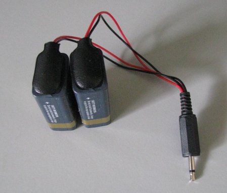
For long-running use, it is recommended that the external power source be a DC bench power supply running off mains power (most electronics stores can sell you such a bench power supply or a kit to build your own). An alternative is to use two 9 volt batteries wired in series to generate an input of 18 volts. 9 volt batteries don't hold a lot of charge, so they may only be suitable for a few hours of use. But that may be enough for casual use if you only program a PIC every few weeks or months. The series connection between the two battery clips is insulated and secured inside the plug housing:
This design is not the only way that 13 volts could be generated, but it is one of the simplest. See the page on alternative 13 volt power supplies for 5V to 13V DC-to-DC step up converter designs that have been contributed by community members.
The main reason for the two-board design for the PIC programmer was to provide some flexibility in VPP generation. If you come up with a better method, then swap out the bottom board and you're good to go.
We now turn our attention to the main circuit board. The circuit has the following features:
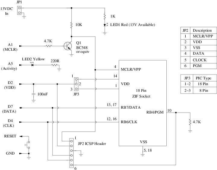
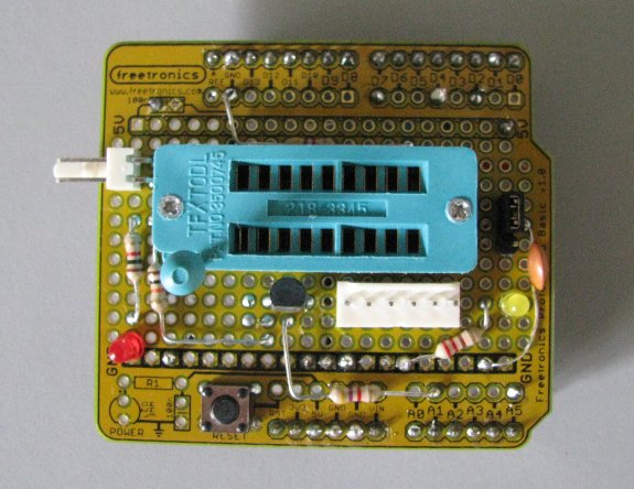
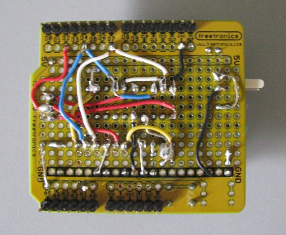
The circuit is built on an Arduino prototyping shield. The following photos show the top and bottom of the main programmer circuit board. The soldering and wiring is a little messy because I made some mistakes in earlier versions of the design and had to correct them (the circuit above is the correct verison):
Modifications may be needed to the circuit for different kinds of PIC's. For example, the PIC16F87 and PIC16F88 have PGM on pin 9 instead of pin 10. You can either modify your shield, or create an adapter cable that plugs into the ICSP header JP2 and remaps the pins appropriately.
If you don't need the ZIF socket because you are only going to be using ICSP mode, then the circuit can be simplified to the following:
This circuit is simple enough that you may be able to build both the 13 volt power supply and the ICSP programmer onto a single shield if you arrange the components carefully. Because a single shield can be top-most, there is no need to lay the components flat. By standing the capacitors and voltage regulator upright, you will get more space for the other components.
The most dangerous part of the programmer circuit is the 13 volt supply. If it is accidentally connected to the wrong pin it could fry the Arduino! Before proceeding, make sure you check the two circuit boards carefully with a multimeter to ensure the following:
Next, plug the two boards into the Arduino but do not connect the external power supply or put a PIC in the ZIF socket yet. Upload the ProgramPIC sketch to the Arduino, launch the Arduino IDE's Serial Monitor, and set the line endings to "Newline".
In the monitor window, type the command PROGRAM_PIC_VERSION (in upper or lower case). If all is well, you should see ProgramPIC 1.0. Next, try the HELP and DEVICES commands. When you issue these commands, the yellow LED should blink briefly. This will verify that the sketch is functioning at a minimal level.
The next step is to attach the external power supply and connect the power supply board to the main board. This is the moment of truth. The red LED should light indicating that VPP is active on the main board.
Place a blank PIC in the ZIF socket (a PIC16F628A is recommended), and launch the Serial Monitor again. This time issue the DEVICE command and you should see something like the following:
Some of the details may be different depending upon the type of PIC you have inserted into the ZIF socket. If you get "ERROR", then there is probably something wrong with the connections on the main board or the jumper shunt on JP3 is in the wrong position. Disconnect all power, inspect the connections on both boards, and try again.
You should now have a working PIC programmer:
Semiconductors:
Resistors:
Capacitors:
Other:
External battery-based power supply (optional):
 1.8.1.2

