This page discusses how to construct and use a noise source based on the jitter from a ring oscillator. The circuit here is very simple: more complex ring oscillator designs are possible and may give better results.
- Note
- The output from a ring oscillator is not generally as good as a "true" noise source. The oscillation can easily settle into regular patterns or sync up with other clock sources on the board. It is even possible to "hack" a ring oscillator by injecting chosen frequencies on the power supply rails to force the oscillation into a predictable waveform (see this paper for an example). It is very important that the output of this class be whitened with RNG before it is used for cryptography and that the device is isolated from attacker-controlled sources of power. Unless you have a very good reason to use a ring oscillator, TransistorNoiseSource is usually a better option.
Ring oscillator theory
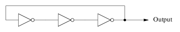
A ring oscillator is formed out of an odd number of inverter gates. A 1 value on the input to the first gate will be inverted several times, resulting in a 0 value being fed back into the first gate. In turn that 0 is inverted several times to generate another 1. And so on. In schematic form, a 3-stage ring oscillator looks like this:
Because electronic circuits are not instanteous devices it can take some time for the values to propagate down the inverter chain. The longer the chain (5-stage, 7-stage, 9-stage, or more) the longer the propagation delay. The important thing is that the delay is not fixed: differences in components, ambient temperature, and other factors combine to introduce a little bit of random jitter in the output waveform.
For our purposes, the jitter is what we are after. The timing differences from one rising edge to the the next gives us the random bits.
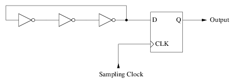
The triangular-shaped output from the final inverter isn't very friendly to microprocessors. So it is common to select out the jitter using a D flip-flop and a periodic clock signal:
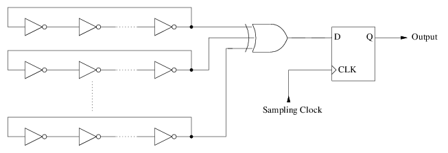
Practical designs inside CPU's often use multiple ring oscillators XOR'ed together:
Even after all that the output won't be uniformly random. It is necessary to whiten the output with a secure hash function before using the data for cryptography. Fortunately for us, RNG.stir() has built-in support for whitening so we just need to collect the raw bits.
Our ring oscillator
To keep things simple, we are going to use a single 5-stage ring oscillator with a sampling clock provided by a 555 timer:
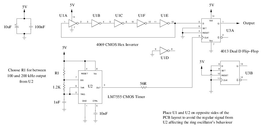
The components were deliberately chosen to be commonly available. The only special one is the 555. I recommend using the CMOS LM7555 variant (or something equivalent) instead because it can operate at higher frequencies than a garden variety 555. The 56 ohm resistor on the output of U2 inhibits ringing on the clock line: we want the noise to come from U1 not U2.
The frequency output from U1 will depend upon the properties of your 4069 chip. A cheap bargain bin chip is actually better than a high quality chip. Some inverter datasheets I have read proudly advertise reduced jitter but the jitter is what we are after here. My 4069 was generating about 1.7MHz with a 5-stage ring oscillator. Other chips I tried were able to exceed 12MHz with a 3-stage ring oscillator. Because the Arduino isn't fast enough to sample high frequency signals, lower is actually better for our needs.
To further lower the frequency to something the Arduino can measure, the 555 timer should be set to between 100kHz and 200kHz (it's ok to be a little over 200kHz). Start with an R1 value of about 2.2K and adjust it up or down to get the frequency into the target range. Also measure the output frequency from U3A and try to target between 20kHz and 50kHz. The Arduino can easily sample that without putting too much burden on the CPU. The signal should be very jittery at this point.
This design can of course be improved by using multiple ring oscillators and an XOR gate, but I wanted to keep the component count low for the basic design.
Parts list
- 1 x 4069 CMOS Hex Inverter
- 1 x 4013 Dual D Flip-Flop
- 1 x LM7555 CMOS Timer
- 1 x 10uF electrolytic capacitor (25V or better)
- 1 x 100nF ceramic capacitor
- 1 x 10nF ceramic capacitor
- 1 x 1nF ceramic capacitor
- 1 x 56 ohm resistor
- 1 x 1.2k ohm resistor
- 1 x 2.2k ohm resistor (or some other value for R1)
Connecting to the Arduino
The RingOscillatorNoiseSource class uses the input capture feature of the AVR microcontroller to measure the time between successive rising edges. Input capture is only possible on certain pins and the output of the circuit above needs to be connected to the correct pin:
| Variant | Arduino Pin / AVR Pin | Timer |
| Arduino Uno | D8 / PB0 | Timer 1 |
| Arduino Leonardo | D4 / PD4 | Timer 1 |
| Arduino Mega or Mega 2560 | D49 / PL0 | Timer 4 |
If your board is not pin-compatible with one of the above, then the source for the RingOscillatorNoiseSource class will need to be modified to use a different pin/timer combination. Also, when the timer is in use by this class it cannot be used for other application tasks.
The timer is set up in free-running mode to count as fast as possible. Whenever a rising edge occurs on the input signal, the timer's current value is written to a special register and an interrupt occurs. Within the interrupt service routine, the previous register value is subtracted from the current value to determine the amount of time that has elapsed between the two rising edges.
The jitter is extracted from the time difference in a very simple way: the lowest bit of the difference is the jitter and all other bits are discarded. The interrupt service routine collects up 16 bits of jitter over successive input pulses and then passes them to the higher level code in the RingOscillatorNoiseSource class.
Within the higher level code, the input bits are first debiased using the Von Neumann method to discard the parts of the signal that don't jitter very much:
- Collect two input bits.
- If they are the same, then discard both.
- If they are different, then choose one as the output bit and discard the other one.
The debiased bits are collected up into a 256-bit buffer. Once the buffer is full it is passed to RNG.stir() to be whitened and incorporated into the global random number pool.
And that's it!
As noted earlier, the output from a ring oscillator is not uniform. To deal with this, the RingOscillatorNoiseSource class takes a fairly conservative approach. It credits a very small amount of entropy to each full buffer, forcing the system to collect more input data to achieve full entropy.
My investigations showed that at 20kHz it takes about a second to generate 256 bits of good random data after Von Neumann debiasing and whitening. Two to three seconds after startup there should be enough entropy in the random number pool to generate encryption keys and other secret material safely. The RNG.available() function can be used to determine when there is enough entropy in the pool for the application's needs.