|
ArduinoLibs
|
|
ArduinoLibs
|
The alarm clock described on this page is a large example application that uses many of the classes in the provided libraries: LCD, Form, Field, SoftI2C, DS1307RTC (or DS3232RTC), Melody and PowerSave. The clock has the following features:
The main clock circuit consists of an Arduino Uno compatible board, a 16x2 LCD module, a realtime clock chip, a piezo buzzer for the alarm, and a MOSFET for controlling the radio:
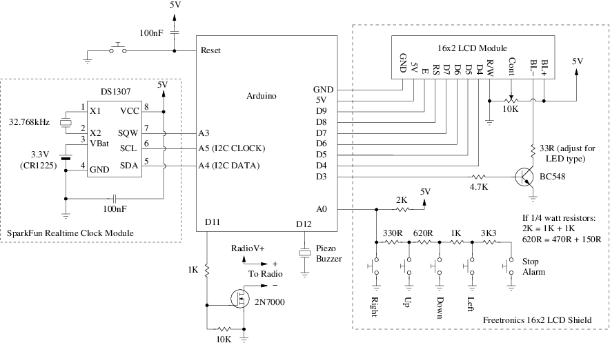
Some of the components can be purchased ready-made as the Freetronics 16x2 LCD Shield and the SparkFun Realtime Clock Module. I used the ready-made realtime clock module, but made my own equivalent to the LCD shield from parts to aid in spacing out the LCD and pushbuttons on the exterior of the box. The value of the 33R resistor may need to be adjusted for different types of back light LED's. See below for information on using a DS3232-based clock module instead of a DS1307-based module.
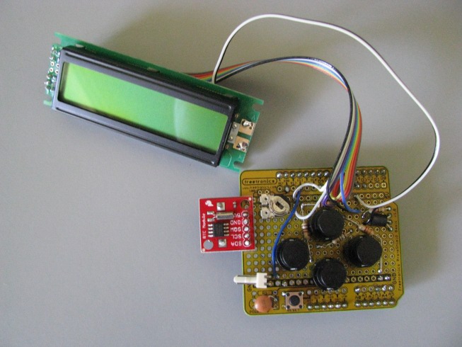
The whole circuit is built on a prototyping shield, with ribbon cables connecting to the LCD. The Stop Alarm button, piezo buzzer, and radio controller are not shown in this picture and some of the components are soldered to the bottom of the shield:
The clock module is based on the DS1307 chip and has an on-board coin battery to keep the time and date ticking over even if the main circuit loses power. The chip is I2C-based and has an auxillary SQW output that can be configured to provide a 1 Hz squarewave signal. This signal is used by the software running on the Arduino to detect when a new time or date is available for display on the LCD. The DS1307RTC class takes care of the details of talking to the chip via I2C.
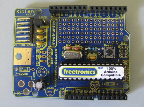
To keep power consumption low, say for being powered by batteries, we don't need a full Arduino Uno or similar board. The USB interface is unnecessary, as is the on-board power supply if there is an external source of 5 volt power. We also don't want the power and D13 status LED's to be draining power. Therefore, a cut-down version of the Arduino is recommended. We used the KitTen kit from Freetronics, and didn't solder up anything that wasn't strictly necessary. A 5v FTDI USB-to-Serial cable is necessary for programming. Similar minimalistic built-it-yourself Arduino designs should also work.
The MOSFET connected to D11 can be used to control the power supply to a separate radio circuit so that the radio can be used as an alarm. In the following circuit, RadioV+ is the radio's power supply voltage (which may be the Arduino's 5V supply if the radio can run off 5V):
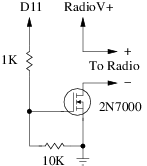
The output of the MOSFET can be used to control almost any kind of circuit; for example an extremely loud mechanical alarm bell. It doesn't have to be a radio. A 2N7000 or equivalent MOSFET is suitable for light loads up to 200mA. For larger currents, a higher-rated MOSFET should be used instead.
Double-tapping the Stop Alarm button will turn the radio on. Single-tapping the Stop Alarm button will turn the radio off. A settings field can also be used to turn the radio on and off.
For clock modules based on the DS3232 chip, such as the Freetronics Real Time Clock Module, change the Clock typedef in Clock.h to the following:
The pads on the Freetronics module should be connected to the Arduino as follows:
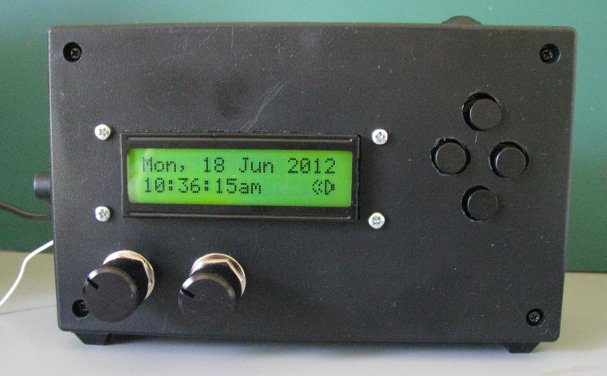
The following picture shows the completed clock prototype, built into a UB1 jiffy box with the radio. Being the prototype, it is a little rough and ready, but rugged enough to take a pounding each morning as a bedside alarm clock:
 1.8.6
1.8.6

