This example shows how to use the BlinkLED and ChaseLEDs classes to simulate the running lights on the starship Enterprise from Star Trek. This can be used as the basis for lighting a model kit. It is recommended that you read the Blink and Cylon tutorials first.
There are four categories of lights on the Enterprise:
- Static lights in windows, engines, and the deflector dish. We don't handle those in this example as we assume that they are connected directly to the power supply with no computer control.
- Red and green navigation lights on the left and right of the saucer, and on the left and right warp nacelles, typically with a 1 second period. The red light is on the left as viewed from the back of the model.
- White strobe light behind the bridge and on the warp nacelles that comes on briefly every second.
- Nacelle lights that perform a circular LED chase in the front of the nacelles to create the warp engine twirl effect.
Different models of the Enterprise have the lights in different places, and the period of flashing can vary from TV show to show, and sometimes from episode to episode. There isn't a definitive set of blink timings or number of LED's in the nacelle chase. The sketch has a number of configurable parameters that gives the user the freedom to choose which show and/or episode they wish to treat as "canonical" for their model.
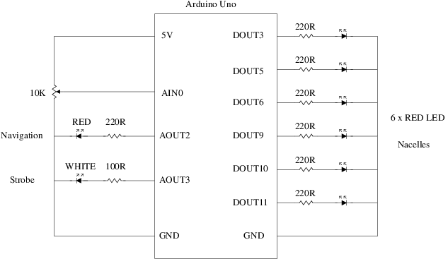
We start by building a test circuit with a small number of LED's for each of the three categories (navigation, strobe, and nacelles):
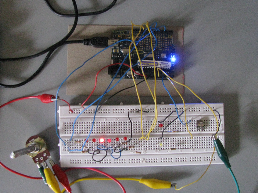
This won't be the final circuit for the model, but building it on a breadboard will help with the initial prototyping stages and choosing the appropriate blink timings:
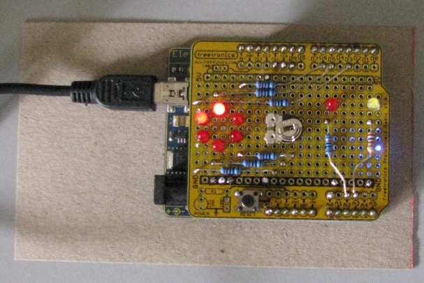
Alternatively, the test circuit can be built on a prototyping shield with the chase LED's in a circular arrangement to simulate how they will look when placed in the front of the model's warp nacelles:
Now that we have a circuit, let's configure the red navigation LED on AOUT2 using the BlinkLED class, to blink with a period of 1000 milliseconds on, 1000 milliseconds off:
#include <BlinkLED.h>
#define NAV_LIGHTS A2 // Output pin for controlling the navigation lights
#define NAV_LIGHTS_ON 1000 // Time the navigation lights are on (milliseconds)
#define NAV_LIGHTS_OFF 1000 // Time the navigation lights are off (milliseconds)
BlinkLED navLights(NAV_LIGHTS, NAV_LIGHTS_ON, NAV_LIGHTS_OFF);
We repeat the process for the strobe LED on AOUT3, with a period of 70 milliseconds on, and 830 milliseconds off:
#define STROBE_LIGHT A3 // Output pin for controlling the strobe
#define STROBE_LIGHT_ON 70 // Time the strobe light is on (milliseconds)
#define STROBE_LIGHT_OFF 830 // Time the strobe light is off (milliseconds)
BlinkLED strobeLight(STROBE_LIGHT, STROBE_LIGHT_ON, STROBE_LIGHT_OFF);
We also need to arrange for BlinkLED::loop() to be called from the application's main loop() function:
void loop() {
navLights.loop();
strobeLight.loop();
}
If you run the sketch at this point, you should see the navigation and strobe LED's blink with the selected rates.
Next is the twirl effect in the warp nacelles, using the ChaseLEDs class. We are actually going to inherit from ChaseLEDs to create a custom LED chaser that reads the chase rate from AIN0 and uses PWM outputs to create a trailing flame effect. See the Cylon example for more information on creating custom effects with ChaseLEDs.
#define NACELLE_CHASE_LEN 6 // Length of nacelle chase, 1..6
#define NACELLE_MIN_PERIOD 25 // Minimum time to advance the nacelle chase (milliseconds)
#define NACELLE_MAX_PERIOD 250 // Maximum time to advance the nacelle chase (milliseconds)
#define NACELLE_DIM_VALUE 32 // Value for dimming previous LED in chase, 0..255
byte nacelleChasePins[6] = {3, 5, 6, 9, 10, 11};
{
public:
NacelleChaseLEDs(const byte *pins, int num)
protected:
void advance(byte prevPin, byte nextPin) {
analogWrite(prevPin, NACELLE_DIM_VALUE);
digitalWrite(nextPin, HIGH);
setAdvanceTime(map(analogRead(NACELLE_RATE), 0, 1023, NACELLE_MIN_PERIOD, NACELLE_MAX_PERIOD));
}
};
NacelleChaseLEDs nacelleChase(nacelleChasePins, NACELLE_CHASE_LEN);
We also need to add a call to ChaseLEDs::loop() to the application's main loop:
void loop() {
navLights.loop();
strobeLight.loop();
nacelleChase.loop();
}
Running the sketch now should cause the six LED's in the nacelle sequence to chase, in addition to the navigation and strobe LED's. The 10K potentiometer can be used to select the desired chase rate. This completes the test circuit, and will allow you to fiddle with the blink timings and chase rate until you are happy with the result.
We've made provision in this sketch for six outputs in the chase, but some models may only use three or five. The NACELLE_CHASE_LEN parameter controls the length of the chase.
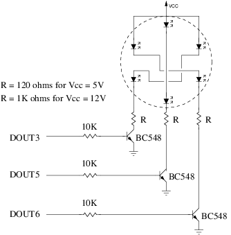
With three outputs, the LED's can be arranged in opposite pairs, lighting two LED's at a time. The following circuit demonstrates how three outputs can be used to drive six LED's:
You will need two of these circuits, for the left and right warp nacelles. The transistor drivers reduce the current load on the Arduino CPU and provide the option to drive the LED's from 12V instead of 5V.
It is recommended that you use transistor drivers for the navigation and strobe lights as well as there will be multiple LED's on each output in a real model. For example, there will be at least three each of the red and green navigation lights: the top of the saucer section, the bottom of the saucer section, and the top of the warp nacelle. Using a 12V supply will make it easier to string lots of LED's together in series.
Other nacelle effects are possible by modifying the advance() method in the sketch. For example, the "opposite pairs" effect with 3 outputs can also be done with 6 outputs and the following modification to the sketch:
void advance(byte prevPin, byte nextPin) {
digitalWrite(previousPin(5), LOW);
analogWrite(previousPin(4), NACELLE_DIM_VALUE);
digitalWrite(previousPin(3), HIGH);
digitalWrite(previousPin(2), LOW);
analogWrite(prevPin, NACELLE_DIM_VALUE);
digitalWrite(nextPin, HIGH);
setAdvanceTime(map(analogRead(NACELLE_RATE), 0, 1023, NACELLE_MIN_PERIOD, NACELLE_MAX_PERIOD));
}
The full source code for the example, including the "opposite pairs" effect, follows:
#include <BlinkLED.h>
#include <ChaseLEDs.h>
#define NACELLE_RATE A0 // Analog input for reading the nacelle chase rate
#define NAV_LIGHTS A2 // Output pin for controlling the navigation lights
#define STROBE_LIGHT A3 // Output pin for controlling the strobe
#define NAV_LIGHTS_ON 1000 // Time the navigation lights are on (milliseconds)
#define NAV_LIGHTS_OFF 1000 // Time the navigation lights are off (milliseconds)
#define STROBE_LIGHT_ON 70 // Time the strobe light is on (milliseconds)
#define STROBE_LIGHT_OFF 830 // Time the strobe light is off (milliseconds)
#define NACELLE_CHASE_LEN 6 // Length of nacelle chase, 1..6
#define NACELLE_MIN_PERIOD 25 // Minimum time to advance the nacelle chase (milliseconds)
#define NACELLE_MAX_PERIOD 250 // Maximum time to advance the nacelle chase (milliseconds)
#define NACELLE_DIM_VALUE 32 // Value for dimming previous LED in chase, 0..255
byte nacelleChasePins[6] = {3, 5, 6, 9, 10, 11};
{
public:
NacelleChaseLEDs(const byte *pins, int num)
protected:
void advance(byte prevPin, byte nextPin) {
analogWrite(prevPin, NACELLE_DIM_VALUE);
digitalWrite(nextPin, HIGH);
setAdvanceTime(map(analogRead(NACELLE_RATE), 0, 1023, NACELLE_MIN_PERIOD, NACELLE_MAX_PERIOD));
}
};
NacelleChaseLEDs nacelleChase(nacelleChasePins, NACELLE_CHASE_LEN);
BlinkLED navLights(NAV_LIGHTS, NAV_LIGHTS_ON, NAV_LIGHTS_OFF);
BlinkLED strobeLight(STROBE_LIGHT, STROBE_LIGHT_ON, STROBE_LIGHT_OFF);
void setup() {
pinMode(13, OUTPUT);
digitalWrite(13, LOW);
}
void loop() {
navLights.loop();
strobeLight.loop();
nacelleChase.loop();
}
 1.8.6
1.8.6

